| .. | ||
| can_arduino_mini_pcb | ||
| panel | ||
| pcb_kicad.png | ||
| README.md | ||
OBUS PCB
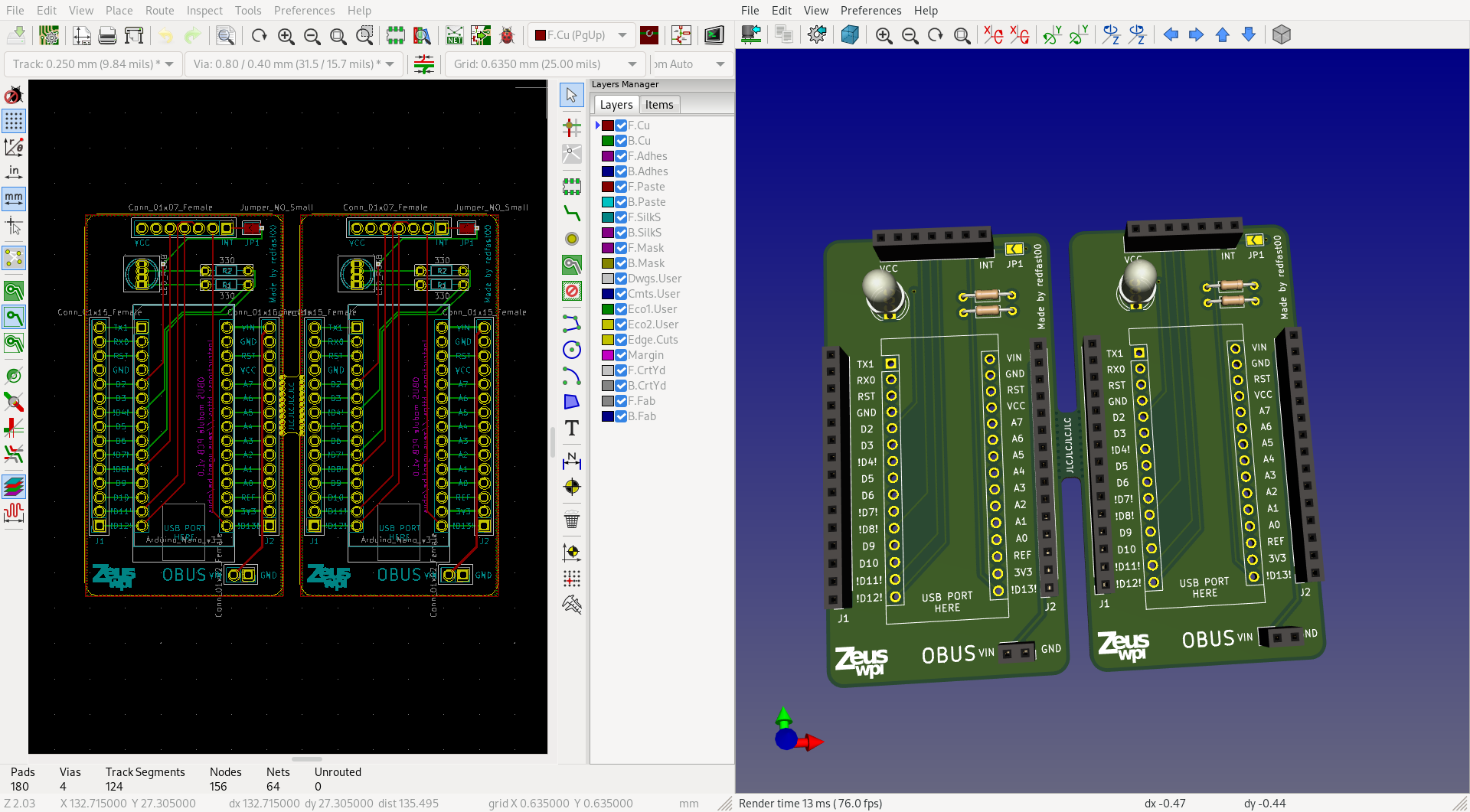
In order to make it easier for our members to get started creating their own OBUS module, we designed and ordered PCBs they can use instead of having to wire up the basics on a breadboard. The PCB accomodates an Arduino Nano V3 (and clones), an MCP2515 CAN-bus module and an RGB LED. The LED and CAN bus module are connected to pins on the Arduino Nano. All pins on the Arduino Nano are connected to the ajacent pin socket so they can easily be accessed when breadboarding. The pins already used by the OBUS framework are marked with exclamation marks. This does not mean they can't be used for other purposes anymore, just that you need to pay attention when using them: for example the SPI pins can be used for other devices, but the LED pins can't. While picking the pins, we made sure to use the least useful pins for the OBUS framework: we tried to pick as few PWM pins as possible, didn't pick any I2C pins, ...
Connecting the parts on the socket.
We tried our best to make the board as self-explanatory as possible. When pushing the Arduino into its socket, make sure it's in the correct orientation. When connecting the CAN bus module, you'll need to flip it on its back, then look at the silk screen on both the OBUS PCB and the CAN module so that the INT pin is connected in the INT socket hole.
By default, the INT pin on the CAN module is not connected to the Arduino in order to save pins. If you want to connect the INT pin to pin D2 on the Arduino, you can bridge the jumper on the top right of the board with some solder.
Getting this board manufactured
I order to get this board manufactured cheaper, we panelized it (by putting two OBUS PCBs per ordered "board"). If you want to manufacture this board, there's a file panel/can_arduino_mini_pcb_panel/fabricate/handin.zip containing all the
Gerber files needed for production. If you modify the original PCB, you can generate
the panel with panel/build.sh, then use KiCAD to plot the Gerber files.
Component list per board
- 2 1x15 2.54mm pin sockets, we recommend 4 sockets so you can socket the Arduino as well
- 1 1x07 2.54mm pin socket
- 1 1x02 2.54mm pin socket
- 1 common cathode 5mm RGB LED, pin order RCGB
- 2 330 ohm through hole resistors